Measure
Phase currents and rotor position feed the control loop. Sensing is part of the electrical design, not an afterthought.

T03 / POWER ELECTRONICS
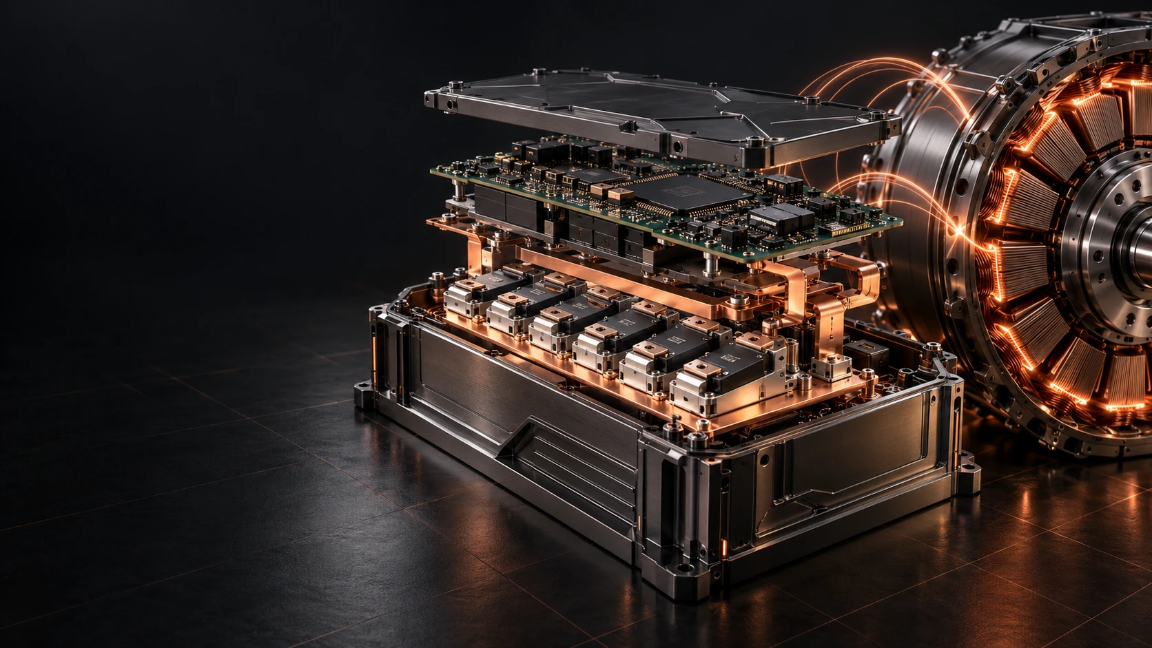
Mag‑FOC™Control that connects command to torque. A modular architecture for managing current, position and power conversion in AeroMag electric motors.
Explore the technologyAI-generated concept visual · illustrative architecture
01 / Mag‑FOC™
Every change in torque starts with a chain of measurements and decisions: acquire phase currents, establish rotor position and command the power stage. Mag‑FOC brings these functions into a platform designed alongside the electric machine.
Phase currents and rotor position feed the control loop. Sensing is part of the electrical design, not an afterthought.
Clarke and Park transformations express the currents in a rotor-aligned reference frame, making the machine command easier to regulate.
Current regulators process the error against their references. Modulation converts the requested voltages into inverter switching commands.
Overcurrent protection, thermal supervision and functional testing support the power conversion chain throughout its lifecycle.
03 / Inside the technology
Move the electrical angle: the d–q frame follows the rotor while the three normalised currents change in the stationary frame.
id = 0 · iq = 1 p.u.
Educational mathematical model: i_d = 0, i_q = 1 p.u. Ideal balanced currents; this is neither Mag‑FOC firmware nor a simulation of its performance.
02 / Design specifications
Reference values from the April 2025 manuals. Design envelopes, not qualification results for the current product. Operating conditions must be established for each variant.
| Family | DC bus | Continuous / peak current | Design context |
|---|---|---|---|
| R‑Series100 | 48–100 V | 300 A / 450 A | Mobility · low-voltage systems |
| A‑Series800 | 400–1,000 V | 400 A / 650 A | Propulsion · high-voltage systems |
Motor output power cannot be inferred by multiplying the endpoints in these columns. Voltage, current, cooling and peak duration need a common, verified operating point.
ENGINEERING / Mag‑FOC™
Current and position
d–q current loops
Modulation and power
Protection and calibration
04 / One engineering ecosystem
AeroMag Forge connects the machine project with materials and controls. These two technologies explain its physical foundations.
REINVENTY / PARTNERSHIP
From voltage class to torque profile: define the control system around the machine.
Request a technical briefing ↗Formulations, process details and application documentation remain within the partnership pathway. Intellectual-property information follows the official disclosure. Intellectual property ↗
Content based on the technical guides: Mag‑FOC rev. 0.1, Materials Dossier rev. 1.0 and Motor Build Manual rev. 0.1 (April 2025). The visuals do not document built hardware or bench tests.