Conventional permanent‑magnet drives struggle to deliver high torque density and ultra‑low iron losses in the tight packaging envelopes demanded by next‑generation e‑mobility and aerospace platforms. Researchers lack an open, replicable reference design to test advanced materials, winding schemes and control strategies.
Why this case study
This page introduces PPMT (Parallel Path Magnetic Motor), a 12‑pole research motor developed by Reinventy Solutions. We release a complete CAD model, geometry and bill of materials based on standard Fe‑Si laminations and copper windings.
Note: Reinventy’s proprietary know‑how concerns the composite material AeroMag™ and the advanced control electronics, which are not included in the open package. The shared prototype is a starting point for researchers to experiment with alternative stators, windings or custom firmware.
From Nikola Tesla to Joe Flynn – the genealogy of PPMT
In 1888 Nikola Tesla presented “A New System of Alternate‑Current Motors and Transformers” to the American Institute of Electrical Engineers, describing the rotating magnetic field that underpins modern electric motors. That same year he secured patents US 381 968 – “Electro‑Magnetic Motor” and US 390 721 – “Dynamo‑Electric Machine” for polyphase synchronous and induction machines.
In the 1990s U.S. engineer Charles “Joe” Flynn filed patent US 5 455 474 – “Magnetic Motor Construction” (1995). Flynn showed that a small steering coil in a parallel magnetic path can divert permanent‑magnet flux with just a few dozen ampere‑turns, yielding four‑fold force gains over conventional solenoids.
This concept, later dubbed Parallel Path Magnetic Technology (PPMT), has been analysed by several academic and industrial teams, including the University of Latvia (Dirba & Kleperis, 2011) and QM Power Inc.
Reinventy’s PPMT motor continues this lineage, linking Tesla’s induction machines to Flynn’s controllable flux paths and today’s open‑source platform.
Tesla has contributed more to electrical science than any man up to his time..
Lord Kelvin, President of the Royal Society, address to the Institution of Electrical Engineers (1896)
Tesla legacy note: Tesla foresaw that electromagnetic machines would one day “operate with very high efficiency and minimal electric input, drawing their principal power from magnetic interactions in the motor itself” (Electrical Engineer, Aug 1891). PPMT embodies that vision by exploiting permanent‑magnet energy while requiring only milliwatts for flux steering.
What is Parallel Path Magnetic Technology
PPMT uses two or more permanent magnets in parallel paths. A low‑power steering coil (0.3–0.5 W) shifts flux between paths, delivering:
Four‑times higher magnetic force for the same excitation energy;
High torque from zero speed with minimal heating;
The ability to hold position with zero current between actuation pulses.
Lab tests on linear and radial demonstrators confirm that, for the same magnets, PPMT delivers about four units of force with the coil on, versus two units in the neutral state.
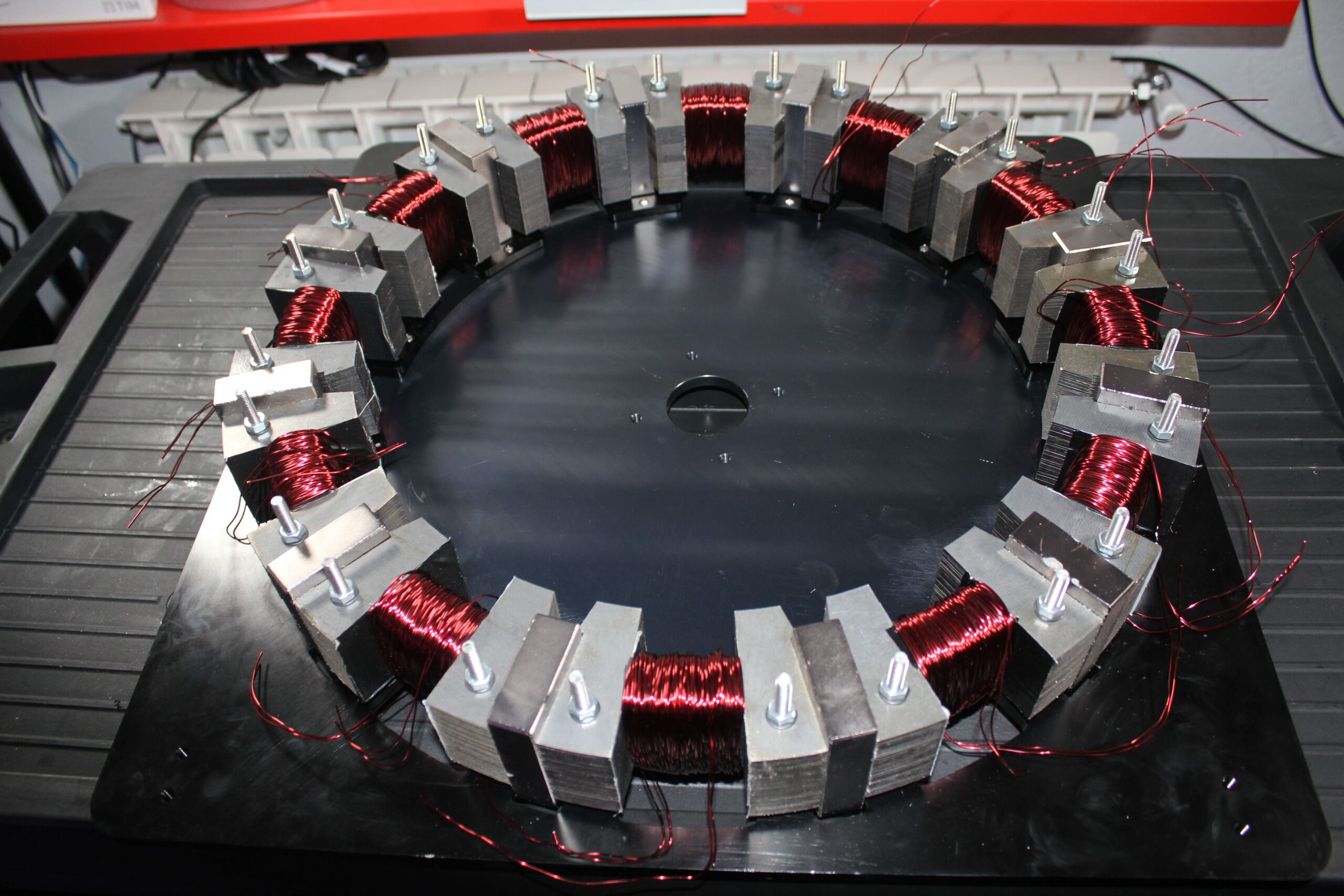
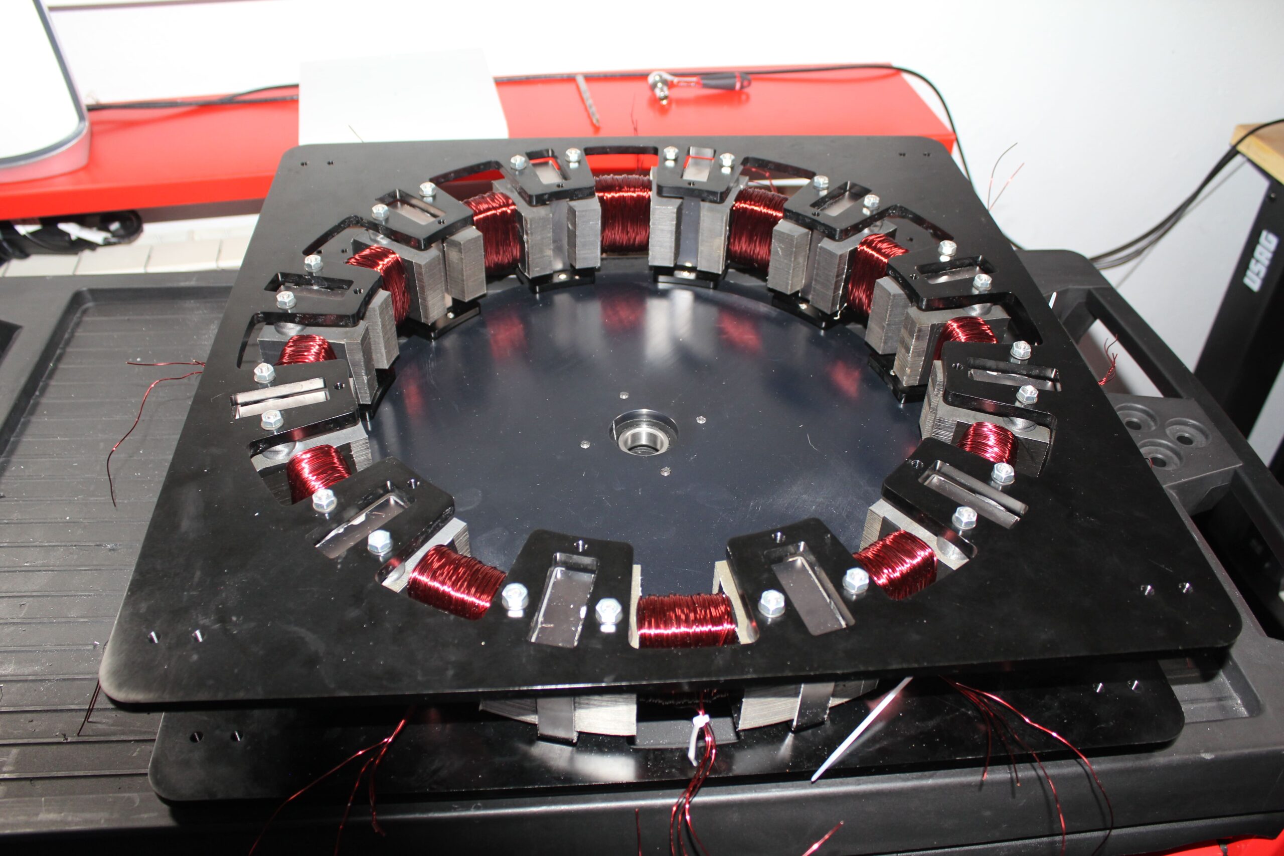
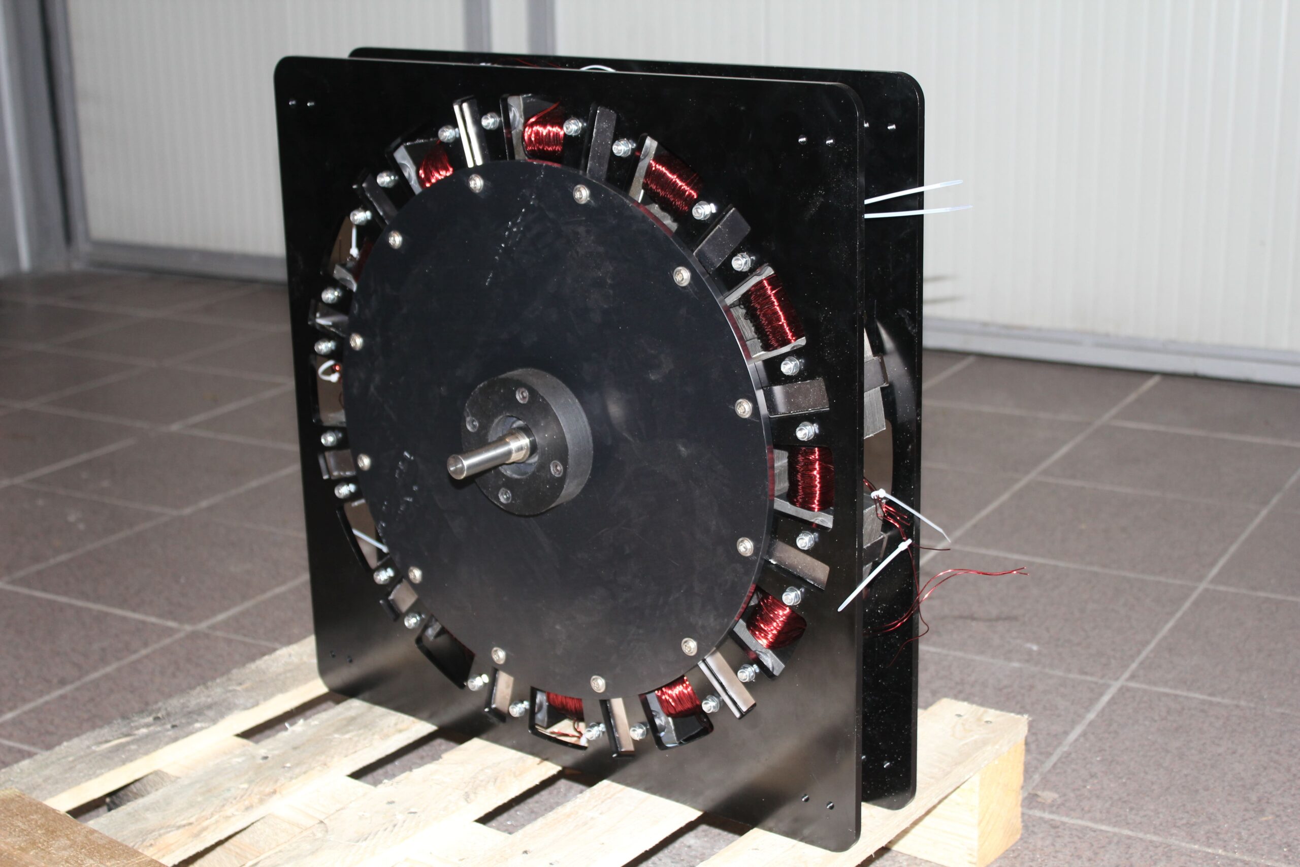
12-pole PPMT motor architecture
Parameter
Value
Stator diameter (Fe-Si laminations)
180 mm
Number of poles
12
Magnets per pole
1 (NdFeB N52 70 × 50 × 18.9 mm)
Flux per magnet
≈ 5 mWb
Steering-coil voltage
0.4 V dc (per coil)
Nominal coil current
1 A
Coil resistance
0.41 Ω
Excitation power (per coil)
0.4 W
Peak torque (design)
> 120 Nm
Continuous speed range
0 – 10 000 rpm
Target efficiency
> 90 %
Magnet note – The 12 NdFeB blocks deliver a combined flux of ≈ 60 mWb. Their BHmax (N52) is ~0.46 MJ m⁻³, storing ~3.5 kJ of magnetic energy.
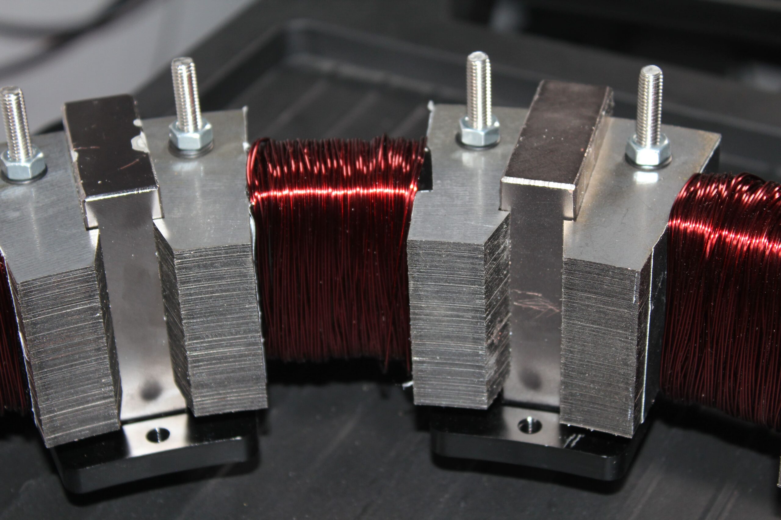
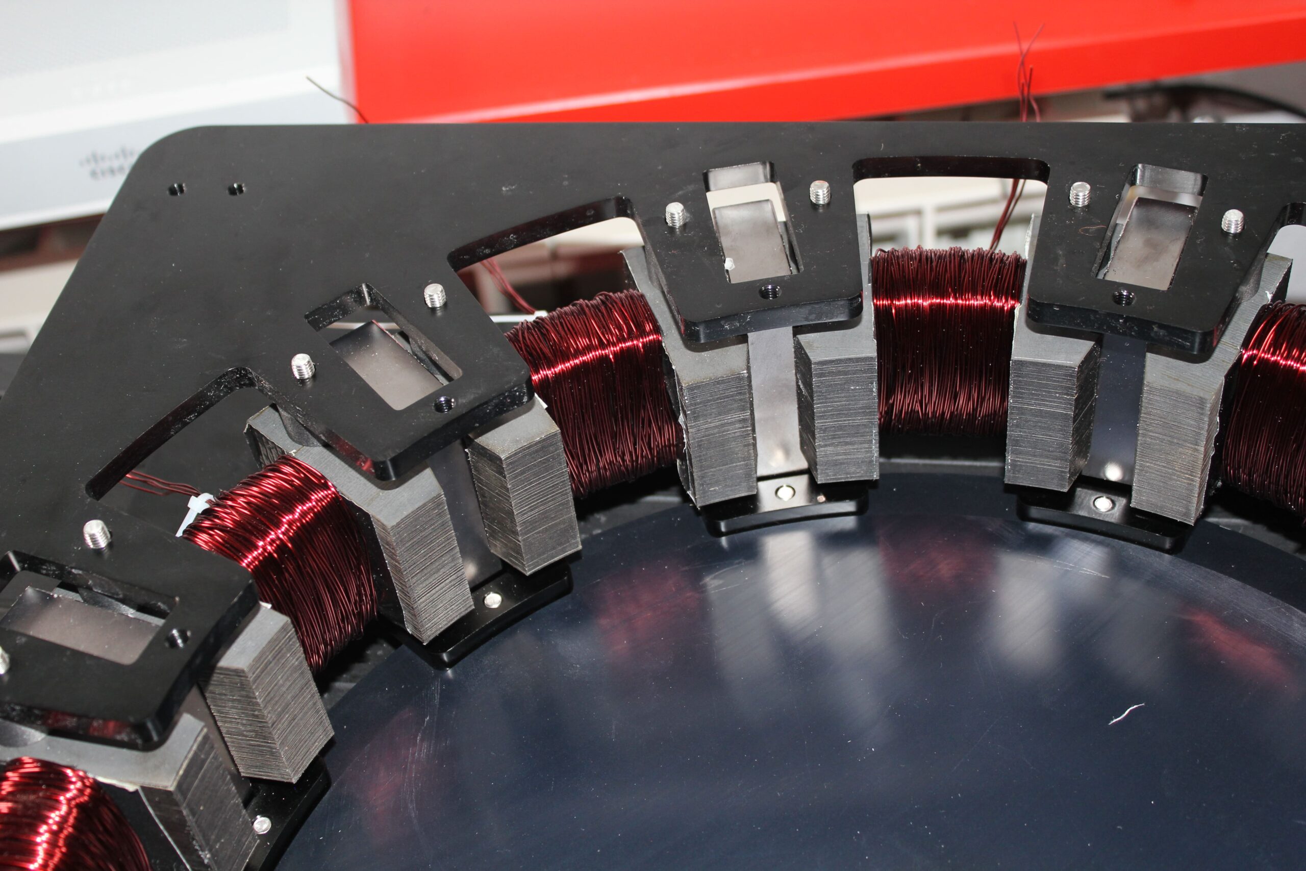
Steering coils – Each coil is 50 turns of bifilar copper Ø 0.8 mm (drawing 013-09-20-13). At 1 A it provides ~50 A-turns and a 0.1 T flux shift, enough to quadruple pole force.
Power balance – At 10 000 rpm and 120 Nm the theoretical mechanical power is ~126 kW. Electrical power for all coils is < 5 W (12 × 0.4 W), illustrating PPMT’s magnet-powered nature.
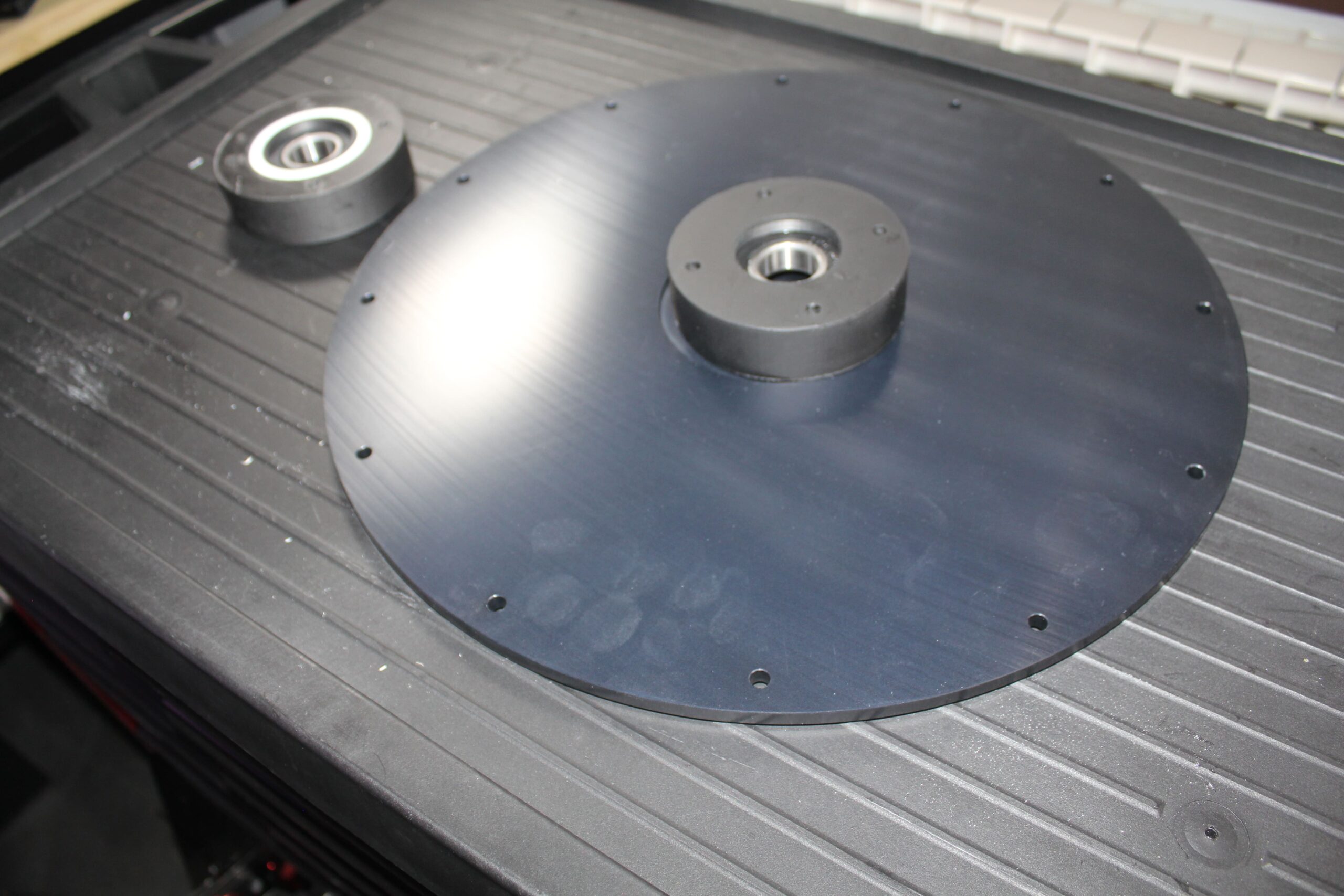
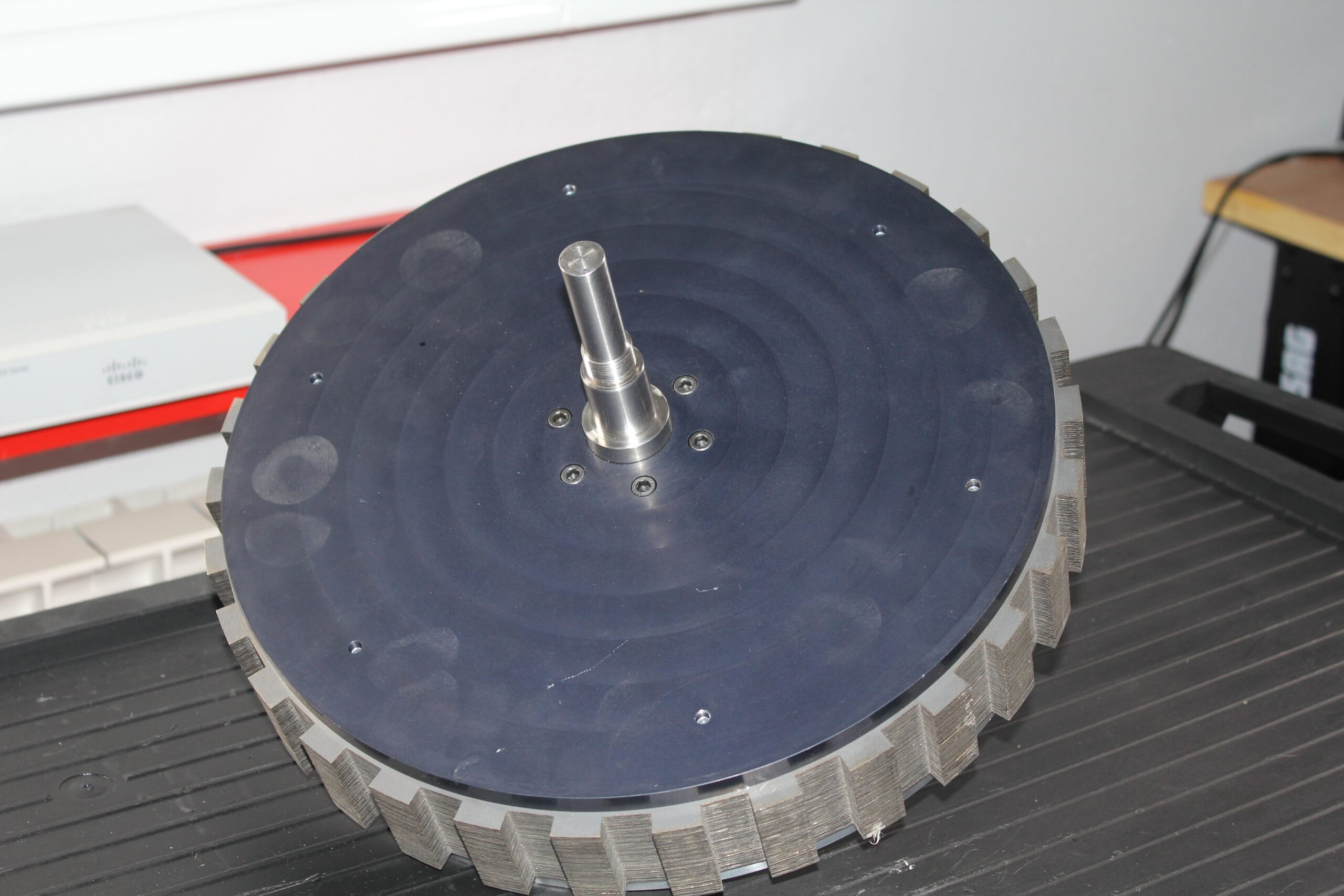
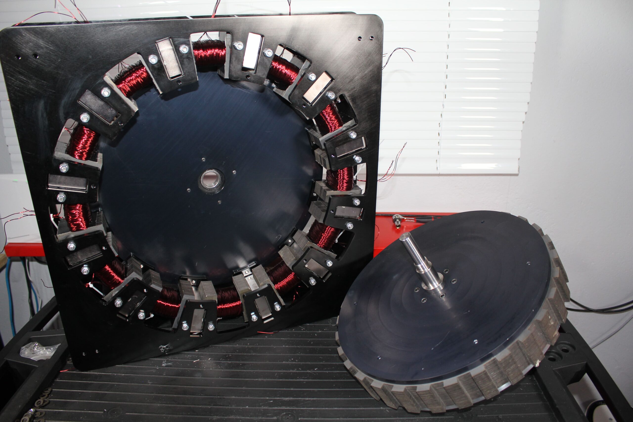
Rotor & stator build – The rotor stack (drawing 013-09-20-17) consists of laser-cut ferromagnetic laminations (0.35 mm ferrite-Si) pressed on a steel hub. Between each stator pair sits a radially oriented NdFeB magnet, as shown in the general assembly. The stators (0.35 mm ferrite-Si – drawing 013-09-20-11) are also laser-cut stacks clamped with brass tie-rods.
Operating parameters (summary)
PPMT uses two or more permanent magnets in parallel paths. A low‑power steering coil (0.3–0.5 W) shifts flux between paths, delivering:
Four‑times higher magnetic force for the same excitation energy;
High torque from zero speed with minimal heating;
The ability to hold position with zero current between actuation pulses.
Lab tests on linear and radial demonstrators confirm that, for the same magnets, PPMT delivers about four units of force with the coil on, versus two units in the neutral state.
Operating parameters (summary)
Item
Value
Coil resistance
0.41 Ω
Nominal coil current
1 A
Nominal coil voltage
0.4 V
Power per coil
0.4 W
Total steering power (12 coils)
4.8 W
Single-magnet flux
5 mWb
Total machine flux
60 mWb
Peak torque (design)
> 120 Nm
Mechanical power @ 10 k rpm
~126 kW
Key benefits
Reinventy’s PPMT prototype translates the parallel‑path concept into tangible, real‑world gains for e‑mobility and industrial drives:
30 – 50 % CO₂ reduction on WLTP cycle versus equivalent motors;
High power density via Parallel Path topology and N52 magnets;
Near‑zero maintenance and silent operation;
Configurable for hybrid‑assist or full‑electric without gearboxes.
CO₂ reduction on WLTP versus baseline
0%
Smaller package than comparable PM drives
0%
Roadmap
To help partners and research teams align their own development cycles, we publish a transparent, quarter‑by‑quarter schedule. Each milestone marks when specific deliverables—hardware builds, documentation drops, field‑test invitations—become available. The table gives a clear view of when you can download new design iterations, submit feedback, or transition from lab evaluation to pre‑series pilot production.
Phase
Q2 2025
Q3 2025
Q4 2025
2026
Lab prototype v1
Open Replication launch
Community field test
Industrial release PPMT v2
Social‑Share Notice —
You are welcome to share this page on social networks as‑is. Any alteration,
partial extraction or re‑hosting of the content requires prior written consent from
Reinventy Solutions Corp. By clicking a share button you acknowledge that:
• Reinventy Solutions is not responsible for comments, interpretations or re‑use made by third parties.
• All specifications are preliminary and may change without notice; shared links should therefore cite the original URL.
• This limited permission does not convey any licence to our trademarks, images or technical data beyond the
context of the original page.
See the full
Master Technology & Commercial Disclaimer
.
Get Started Contact our experts for info, insights or demo material. Email: ppmt@reinventy‑solutions.ca Phone: +1 778 404 0050